
 Close
CloseZeta potential on the surface of a fiber
2.Principle of surface zeta potential measurement method for flat sample
The zeta potential on a flat surface or a sheet-shaped sample is indirectly measured from Mori and Okamoto's equation2) by using the electroosmotic flow in the liquid generated by the potential on sample surface.
(1) Electroosmotic flow
Generally, a quartz cell is used for the measurement cell, but the isoelectric point of quartz is pH 2 to 3, and the surface of the cell is usually negatively charged, so there are many positively charged ions in the solution near the inner wall of the cell. When a voltage is applied to the cell, the positive ions near the cell wall are attracted to the cathode side and move to generate a flow. Since the cell is usually a closed system, the flow near the cell wall will be refluxed, and a reverse flow will occur near the center of cell. This flow inside the cell is called an electroosmotic flow (Fig. 1).
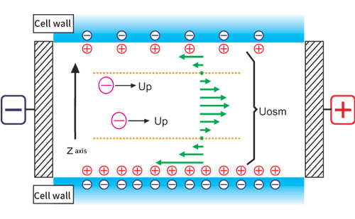
Figure 1. Conceptual diagram of electroosmotic flow
Fig. 2 shows a schematic diagram of the cell for measuring the surface zeta potential of a flat plate sample.
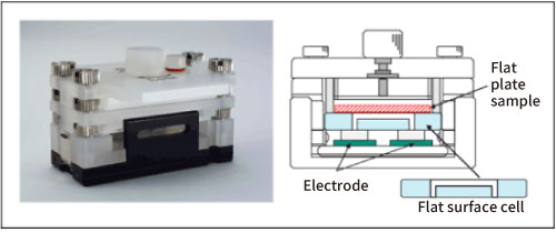
Figure 2. Flat surface cell
The structure is such that a flat plate-shaped or sheet-shaped sample is adhered to the lower surface of a box-shaped quartz cell, and a monitor particle suspension is injected inside the cell. As standard monitor particles, polystyrene latex (particle diameter of about 500 nm) is coated with hydroxypropyl cellulose to reduce the zeta potential to almost zero. Electrophoretic measurements of monitor particles are performed at each position in the cell depth direction. Since the zeta potential of the monitor particles is almost zero, the electroosmotic flow represents the flow generated by the charge state of the cell top surface and the flat plate sample. In addition, in order to reduce the vertical change in electroosmosis mobility and improve accuracy, the inner wall of the flat surface cell is coated with polyacrylamide to reduce the charge to almost zero.
(3) Mori-Okamoto’s equation
Several theoretical formulas with different boundary conditions have been reported for the analysis of electroosmotic flow 3-5). But here, in a rectangular parallelepiped cell, the following Mori and Okamoto equation, which is modeled when the flow velocities of the upper and lower surfaces are different is used.
Uobs(Z) = AU0(Z/b)2 +ΔU0(Z/b) + (1-A)U0 +Up
Uobs(Z):Apparent velocity measured at position y
Z:Distance from cell center
A=1/[(2/3)-(0.420166/k)]
k=a/b:Ratio of side lengths a and b of the cell cross section (a> b)
Up:True particle mobility
Uo:Average flow velocity of the solvent on the upper and lower surfaces of the cell
ΔUo:Difference in the flow velocity of the solvent on the upper and lower surfaces of the cell
Here, the position where Uobs = Up is called the stationary layer (stationary level), and the observed mobility is the true mobility of the particles. Therefore, when the cell depth is smaller than the cell width (k ≧ 5), after measuring the mobility at each cell position by moving up and down the measurement position, the true mobility of the particles(Up) is analyzed by approximating the data by the least squares method and comparing the coefficient. At the same time, the average flow velocity of the solvent on the upper and lower surfaces of the cell (U0) and the difference in the flow velocity of the solvent on the upper and lower surfaces of the cell (ΔU0) are calculated from this equation. So, the mobility at the upper and lower surfaces of cell can be calculated, and the surface zeta potential of flat plate sample placed on the upper surface can be estimated.
| References | 2) | Hiroyuki Mori, Yoshio Okamoto: Froth flotation, 27,117 1-124 (1980) |
| 3) | Smoluchowski,M.:in"Handbuch der Electrizitat unddesMagnetismus, "L.Greatz,Ed.,Barth,Leipzig,1921 |
|
| 4) | White,P.:Phil.Mag.,7(Suppl.No.155),23(1937) | |
| 5) | Komagata,S.:Res.Electrotech,Lab.(Jpn,).March (1933),p348 |